
The pellet cover is the core component of the diesel engine. The castings require lightweight, compact structure, high dimensional accuracy, and good mechanical properties, which increases the difficulty of casting the castings. Among them, when the upper and lower water jacket sand cores of the particle cover are manufactured according to the traditional core-making process, there are many defects in the inner cavity of the casting, and welding and other defects are likely to occur where the wall thickness of the casting is ≤4 mm, which seriously affects the quality of the casting.
1 Casting structure and process difficulties
1.1 Casting structure and technical requirements
The casting is a four-cylinder diesel engine cylinder head, with a length × width × height of approximately 440 mm × 270 mm × 110 mm. The weight of the part is approximately 40 kg. The basic wall thickness of the part is 4.0 mm. The space between the inlet and exhaust passages is narrow and the size ≤ 4 mm, the casting dimensional accuracy requirement reaches CT8-CT9 level in GB/T 6414. The structure is shown in Figure 1.
The casting material of the cylinder head is RuT450, the body hardness is 200~225 HBW, the creep rate is ≥ 90%, and the body tensile strength is ≥ 450 MPa.
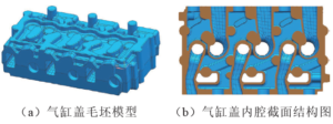
Figure 1 Cylinder head casting and inner cavity structure
1.2 Analysis of casting process difficulties
The shape of the water jacket sand core in the inner cavity of the cylinder head is complex. During the molding process, the sand injection problem is not full in the narrow, conforming curved surface mold parting area with a thickness of ≤ 3.5 mm, resulting in quality problems such as scrapped castings and sintering defects. Especially in the narrow sheet cavity with a thickness of 2.5~3.5 mm, the process is difficult to meet the technical requirements.
Figure 2 is a four-cylinder cylinder head water jacket sand core of a certain model extracted through UG software. The sand core shape part has many matching surfaces and is too small. The thinnest wall thickness of the sand core is ≤ 3 mm. The sand core has low strength and is easy to break. The air passage The small and narrow gaps between them are easy to produce sintering defects and are difficult to clean, causing the water cavity of the casting to be blocked and scrapped.
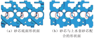
Figure 2 Sand core structure of the water jacket
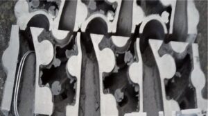
Figure 3 Actual picture of the anatomy of the inner cavity of the cylinder head casting
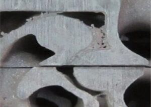
Figure 4 Actual picture of the sintered anatomical part of the inner cavity of the cylinder head casting
The main reasons for the large fitting gap between sand cores and low sand core strength are:
(1) The wall thickness of the sand core is too thin and the placement of the nozzle is unreasonable. The mating surfaces during the mold manufacturing process are manually trimmed, resulting in a large mating gap, resulting in sand runaway, easy ejection of the sand core, and low tightness of the sand core.(2) The cold core process is used to make the core, and the core sand is made of chromite sand. The sand has poor fluidity, which causes the sand core to be easily ejected and full, and the sand core fullness is low.
3.1.1 Optimizing sand shooting simulation technology
In the design stage, simulated sand shooting simulation technology was introduced to improve the accuracy of the design. According to the characteristics of the sand core structure, the local sand core wall thickness is ≤ 3 mm, and the sand injection nozzle and exhaust plug cannot be arranged. Therefore, the sand injection simulation analysis focuses on the thinner sand core wall thickness.
(1) First use the original design model to simulate sand injection. The simulation result is that the sand flow at the black circle position is obviously separated, and there is a phenomenon that the sand injection is not full or not tight. The simulation results are shown in Figure 5.
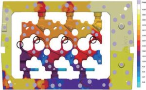
Figure 5 Schematic diagram of original model simulating sand shooting effect
(2) Based on the original model simulation results, multiple rounds of program adjustments and simulations were conducted, and the optimal sand shot design plan was finally determined. The shot sand design plan and simulation results are shown in Figures 6 and 7.
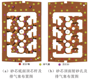
Figure 6 Schematic diagram of the sand core shooting and exhaust arrangement of the lower water jacket
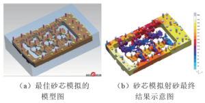
Figure 7 Schematic diagram of the best model to simulate sand shooting effects
The sand shooting nozzle and sand shooting plate designed before optimization are fastened with threads. The structure is complex and the sand shooting effect is average. Moreover, the sand shooting hole is very small and the sand shooting flow rate is small. It cannot guarantee that the shot will be filled within the sand shooting time required by the process. At the same time, because the sand shot hole is small, it is easy to cause the sand shot hole to be blocked.
The optimized sand-shooting nozzle and sand-shooting plate have a mating flange surface with a depth of 5~8 mm, and the flange surface is tightened with screws; the sand inlet at the corresponding position of the sand-shooting plate is conical to facilitate sand shooting. The sand-shooting hole structure is optimized and the sand-shooting hole is enlarged to ensure the sand-shooting flow rate. The structure before and after the optimized design of the sand shooting nozzle is shown in Figure 8 and Figure 9.
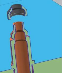
Figure 8 Schematic diagram of the sand injection nozzle before optimization
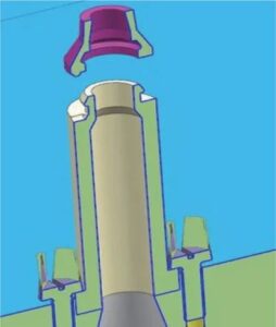
Figure 9 Schematic diagram of the optimized sand shooting nozzle
3.1.3 Introduction of electric spark technology
The mating surface of the manual repair mold is repaired with red red powder. The box sub-surface and the mating surface are each coated with red red powder. The friction traces of the red red powder are observed through the upper and lower core boxes to close the mold, and manual repair is carried out. The gap accuracy is low, as shown in Figure 10.
In the mold repair process, electric spark technology is introduced to replace manual repair. Both the box sub-surface and the mating surface have been processed by EDM. The use of EDM can completely avoid errors caused by manual repairs, ensure the sealing between the mating surfaces, ensure the sand shooting pressure, and ensure that the sand and sand core do not run during sand shooting. No seams.
Repaired by EDM technology, the box-dividing surface and mating surface are processed by EDM, and the mating gap accuracy is ≤ 0.1 mm, as shown in Figure 11.
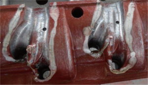
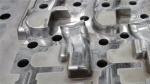
Figure 11 Actual picture of the mold polished by EDM
(1) Continuously shoot multiple sand cores. No sand remains on the mold. There is no sand running when shooting. The sand core is full and tight, with high strength. There are no gaps. No core repair is needed. The sand core yield is ≥98%. As shown in Figure 12.
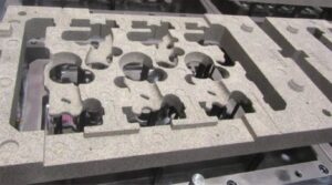
Figure 12 Actual picture of the sand core ejection of the water jacket under the cylinder head
(2) The inner cavity of the casting has no seams, no sand sticking, no sintering, and is easy to clean. The wall thickness of the sand core is ≤3.5 mm. There is no sintering in the position and it is easy to clean. The casting is shown in Figure 13.
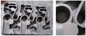
Figure 13 A cutaway view of the inner cavity of the cylinder head casting