In the era of great transformation when the global automotive industry is undergoing energy transition, intelligent upgrading, and fierce market competition, the R & D iteration efficiency of automotive powertrain has become one of the core competitiveness elements for enterprises to establish themselves in the market. Rapid prototyping technology, as a key technology that can significantly shorten the R & D cycle, reduce costs, and improve product quality, is comprehensively reshaping the R & D and production modes of automotive powertrain, injecting new vitality and infinite possibilities into the development of the automotive industry.
Automotive powertrain, as the core part of a vehicle, covers key components such as engines, transmissions, and drive axles. The performance of the powertrain directly determines important indicators such as the power, economy, reliability, and environmental protection of the vehicle. In the past, the traditional R & D process of powertrain was extremely cumbersome and lengthy. From the initial design concept to the final product finalization, it needed to go through multiple complex and time-consuming links. First, the design scheme had to be repeatedly refined and modified, which required engineers to invest a large amount of time and energy to carefully analyze and weigh various design parameters. Then came the manufacturing of molds, which not only had a long cycle but also was costly. Once the design changed, the molds often needed to be remade, which would undoubtedly further increase the investment of time and funds. Subsequently, the production of prototypes was carried out, during which various process parameters needed to be debugged and optimized to ensure that the quality of the prototypes met the requirements. Finally, repeated tests and optimizations of the prototypes were required. Through various simulation tests and actual road tests, problems existing in the design and manufacturing processes were found and solved. According to relevant data statistics, under the traditional R & D mode, the R & D cycle of a new powertrain may be as long as 3 – 5 years, and the cost may be as high as hundreds of millions of dollars.
However, with the rapid change of the market environment, consumers’ demand for new automotive products is becoming increasingly urgent. Automobile manufacturers need to continuously introduce innovative and competitive products to meet the market demand. Meanwhile, the rapid development of digital design and manufacturing technologies has provided new technical means and methods for the R & D of automotive powertrain. Against this background, rapid prototyping technology emerged. It combines advanced digital models, computer-aided design (CAD), computer-aided engineering (CAE) with a series of rapid prototyping and processing technologies, and can transform design drawings into physical prototypes with actual functions in a very short time. The emergence of this technology has provided engineers with an efficient platform for quickly verifying design ideas, finding and solving potential problems, greatly accelerating the R & D process of automotive powertrain.
Sand casting occupies a pivotal position in the field of rapid prototyping of automotive powertrain. Its basic principle is to use sandy materials to make molds, pour liquid metal into the mold cavity, and after the liquid metal cools and solidifies, the required casting can be obtained. The reason why sand casting can be widely used in the rapid prototyping of automotive powertrain mainly benefits from its unique advantages.
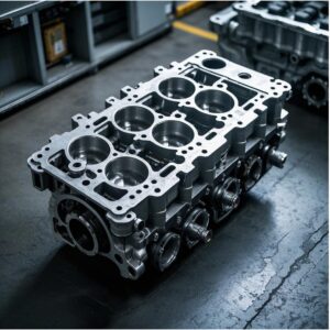
For automotive cylinder blocks, which have extremely complex structures and contain many fine structures such as cooling channels and oil channels, sand casting shows incomparable advantages. On the basis of the traditional sand casting process, with the integration of 3D printing technology in recent years, the sand molding process has been greatly innovated and improved. Through 3D printing sand mold technology, the complex channel structures inside the cylinder block can be accurately constructed. For example, when designing the cylinder block of a high-performance engine, engineers can, based on the results of thermal analysis and fluid dynamics simulation, use 3D printing technology to produce sand cores with specific shapes and sizes. These sand cores can form accurate cooling channels and oil channels in the mold. After the liquid metal is poured into the mold, these sand cores can be removed after the casting is formed, leaving precise internal channels to ensure that the coolant and lubricant can circulate efficiently and stably during the operation of the engine, providing a solid guarantee for the engine to maintain normal working temperature and good lubrication conditions.
In addition, the mold making of sand casting is relatively simple and low-cost. Compared with the manufacturing of some high-precision metal molds, the production process of sand molds does not require complex processing equipment and high material costs. For the rapid prototyping requirements of small batches and multiple varieties, sand casting can respond quickly. By adjusting the design and production process of sand molds, different specifications and structures of automotive powertrain component prototypes can be produced in a short time, providing great flexibility for product R & D and improvement.
Low pressure casting is an advanced casting process in which liquid metal is slowly and steadily filled into the mold cavity under the action of low pressure gas. This process shows significant advantages in the manufacturing process of automotive cylinder heads.
As the core component controlling the intake and exhaust in the engine, the internal structure of the automotive cylinder head is extremely complex, and the requirements for the quality and precision of the casting are almost 苛刻. When the engine is working, the cylinder head needs to withstand high temperature, high pressure, and the corrosion of gas, and at the same time, it needs to ensure the smoothness of intake and exhaust and the close cooperation with other components. The low pressure casting process can effectively reduce defects such as pores and shrinkage cavities inside the casting, ensure the dense and uniform internal structure of the cylinder head, thereby greatly improving its reliability and durability.
During the low pressure casting process, by precisely controlling the gas pressure and filling speed, the liquid metal can fill the mold cavity in a slow and steady manner. This filling method enables the liquid metal to flow more evenly into all corners of the mold, especially for those thin-walled and complex-shaped parts on the cylinder head, such as valve seat rings and spark plug mounting holes, achieving good forming effects. Compared with traditional gravity casting, low pressure casting can significantly reduce the pores and shrinkage cavities inside the casting, improve the density and mechanical properties of the casting. For example, in the low pressure casting process of a high-performance engine cylinder head, by optimizing the gas pressure curve and filling speed, the porosity inside the casting was successfully reduced by more than 50%, and the fatigue strength of the cylinder head was increased by 30%, effectively improving the overall performance and reliability of the engine.
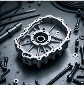
Gravity casting is one of the most basic and widely used casting methods. It mainly relies on the gravity of liquid metal to flow into the mold cavity to complete the casting forming process. In the rapid prototyping of automotive transmission cases, gravity casting plays an indispensable role.
The transmission case, as the outer shell protecting the internal gears, shafts, and other transmission components of the transmission, has a relatively regular structure, but still has certain requirements for dimensional accuracy and surface quality. The gravity casting process has the characteristics of simple operation and low cost, and can quickly produce transmission case prototypes that meet the requirements of prototype testing. In the actual production process, by reasonably designing the mold structure and casting system, the rapid prototyping of the transmission case can be efficiently completed under the premise of ensuring a certain forming quality.
For example, when designing the mold structure, engineers will design reasonable gate and riser positions according to the shape and size of the transmission case to ensure that the liquid metal can evenly fill the mold cavity and achieve good feeding during the solidification process. At the same time, by optimizing the parameters of the casting system, such as casting temperature and casting speed, the quality and performance of the casting can be effectively controlled. In the rapid prototyping of a new automotive transmission case by gravity casting, by adopting the optimized mold structure and casting system, the production cycle of a single case was successfully shortened to within 30 minutes, and the dimensional accuracy and surface quality of the casting both met the design requirements, providing strong support for subsequent performance testing and design optimization.
CNC five-axis machining is a high-precision, high-flexibility advanced machining technology that can accurately machine complex curved surfaces of parts. In the rapid prototyping of key components such as motor housings and electric drive axles of new energy vehicles, the advantages of CNC five-axis machining technology are vividly demonstrated.
The motor housing, as an important structure protecting the internal windings and magnetic steels of the motor, not only needs to have good mechanical strength to withstand the various forces during the operation of the motor, but also needs to have excellent heat dissipation performance to ensure that the motor can maintain a stable working temperature during long-term operation. In addition, to meet the requirements of new energy vehicles for lightweight, the shape and internal structure of the motor housing are often designed to be more complex. CNC five-axis machining technology can complete the machining of multiple surfaces and complex curved surfaces in one clamping, greatly improving the machining accuracy and efficiency. Through the five-axis linkage machining method, the cutter can machine the workpiece at various angles and postures, accurately machining various special-shaped heat dissipation fins, mounting holes, and internal reinforcing ribs on the motor housing, ensuring that the dimensional accuracy and surface quality of the motor housing meet the design requirements, thereby ensuring the efficient operation and reliable heat dissipation of the motor.
For the electric drive axle, it contains a variety of high-precision gear transmission components and shaft parts. The machining accuracy and surface quality of these parts directly affect the power transmission accuracy and stability of the electric drive axle. CNC five-axis machining can accurately machine the complex contours and mating surfaces of these parts. By precisely planning and controlling the tool path, high-precision grinding of gear tooth surfaces and precision turning of shaft parts can be achieved, ensuring the power transmission accuracy and stability of the electric drive axle and meeting the strict requirements of new energy vehicles for high-performance drive systems. For example, in the rapid prototyping of an electric drive axle of a new energy vehicle, by adopting CNC five-axis machining technology, the transmission accuracy of the gears was successfully improved by one level, the noise and vibration of the electric drive axle during operation were reduced, and the driving comfort and reliability of the new energy vehicle were improved.
As the core bearing component of the engine, the quality and performance of the automotive cylinder block directly affect the overall performance of the engine. Rapid prototyping technology provides engineers with an efficient design verification platform, enabling them to quickly verify and optimize different cylinder block design schemes in a short time.
In practical applications, engineers will first use CAD software to conduct three-dimensional modeling design of the cylinder block according to the design requirements of the engine. Then, through rapid prototyping technology, the design model is transformed into a physical prototype. Next, a series of tests simulating the actual working conditions of the engine are carried out on the prototype cylinder block, such as durability tests under high temperature and high pressure, coolant flow simulation tests, and mechanical stress analysis tests. Through these tests, potential problems existing in the design, such as cylinder bore deformation, uneven cooling, and stress concentration, can be found in time.
For example, in the R & D process of a new engine cylinder block, engineers produced multiple cylinder block prototypes of different design schemes through rapid prototyping technology. When conducting a high temperature and high pressure durability test on one of the prototypes, it was found that the cylinder bore had a slight deformation in a specific area. Through the analysis of test data and simulation, engineers found that the root cause of the problem was the unreasonable wall thickness design in this area. Subsequently, they optimized the design scheme, increased the wall thickness in this area, and remade the prototype for testing. After several iterative optimizations, the optimal cylinder block design scheme with the best performance was finally obtained. This rapid verification and optimization process has greatly shortened the R & D cycle of the cylinder block and improved the reliability and performance of the product.
The design of the automotive cylinder head plays a crucial role in the performance of the engine’s intake, exhaust, and fuel injection systems. Different engine combustion strategies and performance requirements need to be matched with different structures of cylinder heads. Rapid prototyping technology enables engineers to quickly produce multiple cylinder head prototypes of different designs, and evaluate the impact of different cylinder head designs on engine performance through various performance tests.
Common test methods include airway flow tests, combustion simulation tests, valve sealing performance tests, etc. For example, when conducting an airway flow test, engineers will install different designed cylinder head prototypes on special test equipment, simulate the intake process of the engine, and measure the flow coefficient and velocity distribution of the airway to evaluate whether the design of the intake airway is reasonable. In the combustion simulation test, CFD (Computational Fluid Dynamics) software is used to simulate and analyze the combustion process under different cylinder head designs to predict combustion efficiency, emission performance, and other indicators. Through these tests and analyses, engineers can have an in-depth understanding of the advantages and disadvantages of different cylinder head designs, and then conduct targeted optimization and improvement.
For example, in the R & D of a high-efficiency and energy-saving engine, engineers produced three cylinder head prototypes with different intake port structures through rapid prototyping technology. After airway flow tests and combustion simulation tests, it was found that one of the cylinder head prototypes with a spiral intake port design could significantly improve the intake efficiency and combustion uniformity, thereby enhancing the power output and fuel economy of the engine. Based on these test results, engineers further optimized this cylinder head design and finally applied it to the mass-produced engine, obtaining good market feedback.
The transmission case not only needs to provide reliable support and protection for the internal gears, shafts, and other transmission components, but also needs to ensure good sealing to prevent lubricant leakage. In the rapid prototyping process, a series of performance tests on the transmission case prototype can be carried out to test whether its design meets the actual use requirements.
Common test items include sealing tests, structural strength tests, vibration and noise tests, etc. In the sealing test, the pressure test method or helium leak detection method is usually used to fill a certain pressure of gas or helium into the interior of the transmission case, and then detect whether there is gas leakage on the surface of the case. In the structural strength test, by simulating the loads borne by the transmission under different working conditions, the finite element analysis software is used to calculate and analyze the stress and strain distribution of the case to evaluate whether the structural strength of the case meets the requirements. If it is found that the prototype has problems such as poor sealing or insufficient strength, the design can be modified in time, and the prototype can be remade for testing.
In addition, rapid prototyping can also help engineers optimize the structural design of the transmission case. On the premise of ensuring performance, the weight of the case can be reduced, the material cost can be reduced, and the overall fuel economy of the vehicle can be improved. For example, in the R & D process of a new transmission case, engineers combined topology optimization technology with rapid prototyping technology to optimize the structural design of the case. On the premise of ensuring that the strength and stiffness of the case meet the requirements, the weight of the case was successfully reduced by 15%, effectively reducing the energy consumption and emissions of the vehicle.
In the field of new energy vehicles, the performance of the motor housing directly relates to the working stability and safety of the motor. The motor will generate a large amount of heat during operation, so the motor housing needs to have good heat dissipation performance. At the same time, to increase the driving range of new energy vehicles, the motor housing also needs to be as lightweight as possible. Rapid prototyping technology enables engineers to quickly produce multiple motor housing prototypes according to different heat dissipation requirements and lightweight design concepts, and evaluate their performance through a series of test methods.
Common test methods include heat conduction tests, modal analysis tests, structural strength tests, etc. In the heat conduction test, a heat source is set inside the motor housing to simulate the heating situation during motor operation, and then infrared thermal imager and other equipment are used to measure the temperature distribution on the surface of the housing to evaluate the heat dissipation performance of the housing. In the modal analysis test, the vibration test of the motor housing is carried out to obtain its natural frequency, vibration mode, and other parameters, evaluate the vibration characteristics of the housing under different working conditions, and avoid structural damage caused by resonance. Through these tests, engineers can have an in-depth understanding of the performance characteristics of different motor housing designs, and then conduct targeted optimization and improvement.
For example, in the R & D of a high-performance electric vehicle motor housing, engineers proposed a design scheme using a new aluminum alloy material combined with the optimization of the heat dissipation fin structure. Multiple motor housing prototypes with different heat dissipation fin structures were produced through rapid prototyping technology, and heat conduction tests and modal analysis tests were carried out. The test results showed that one of the motor housing prototypes with a bionic design of the heat dissipation fin structure had a 30% improvement in heat dissipation performance compared with the traditional design, and its modal performance also met the design requirements. Based on these test results, engineers further optimized the design scheme and finally applied it to the mass-produced vehicle model, effectively improving the working stability and reliability of the motor.
As a key component of new energy vehicles, the performance of the electric drive axle directly affects the power transmission efficiency and handling performance of the vehicle. Rapid prototyping technology can help engineers quickly verify the design scheme of the electric drive axle, including the optimization of gear transmission ratio, the layout design of the shaft system, and the strength and stiffness analysis of the overall structure.
In practical applications, engineers will first use CAD/CAE software to conduct virtual modeling and analysis of the design scheme of the electric drive axle to predict its performance under different working conditions. Then, through rapid prototyping technology, the electric drive axle prototype is produced and tested under simulated vehicle driving conditions. Common test items include power transmission efficiency tests, gear meshing noise tests, shaft system fatigue life tests, etc. Through these tests, problems existing in the design, such as excessive gear meshing noise, low transmission efficiency, and shaft system fatigue fracture, can be found in time.
For example, in the R & D process of a new electric drive axle of a new energy vehicle, engineers produced multiple electric drive axle prototypes with different gear transmission ratios and shaft system layout designs through rapid prototyping technology. During the power transmission efficiency test, it was found that one of the electric drive axle prototypes with an optimized gear transmission ratio and shaft system layout design had an 8% increase in power transmission efficiency compared with the traditional design. In the gear meshing noise test, by optimizing the gear tooth profile and adopting advanced manufacturing processes, the gear meshing noise was successfully reduced by 10 dB(A). After several tests and optimizations, the final design scheme of the electric drive axle that meets the performance requirements of new energy vehicles was determined, providing strong technical support for the industrialization development of new energy vehicles
